Robots to print at home · phase 1: the body · project not yet printed

Your pet robot’s body comes out of your 3D printer

You want a creature-like robot at home. Ready-made kits are expensive, and loose projects from the internet often don’t fit: hours of printing and filament wasted. robos-impressos provides the body: three models with a place for each motor and board, checked by a program before you print (you confirm the fit on your printer with a small test piece). Making it move on its own, with wiring and programming, comes in the next phase.

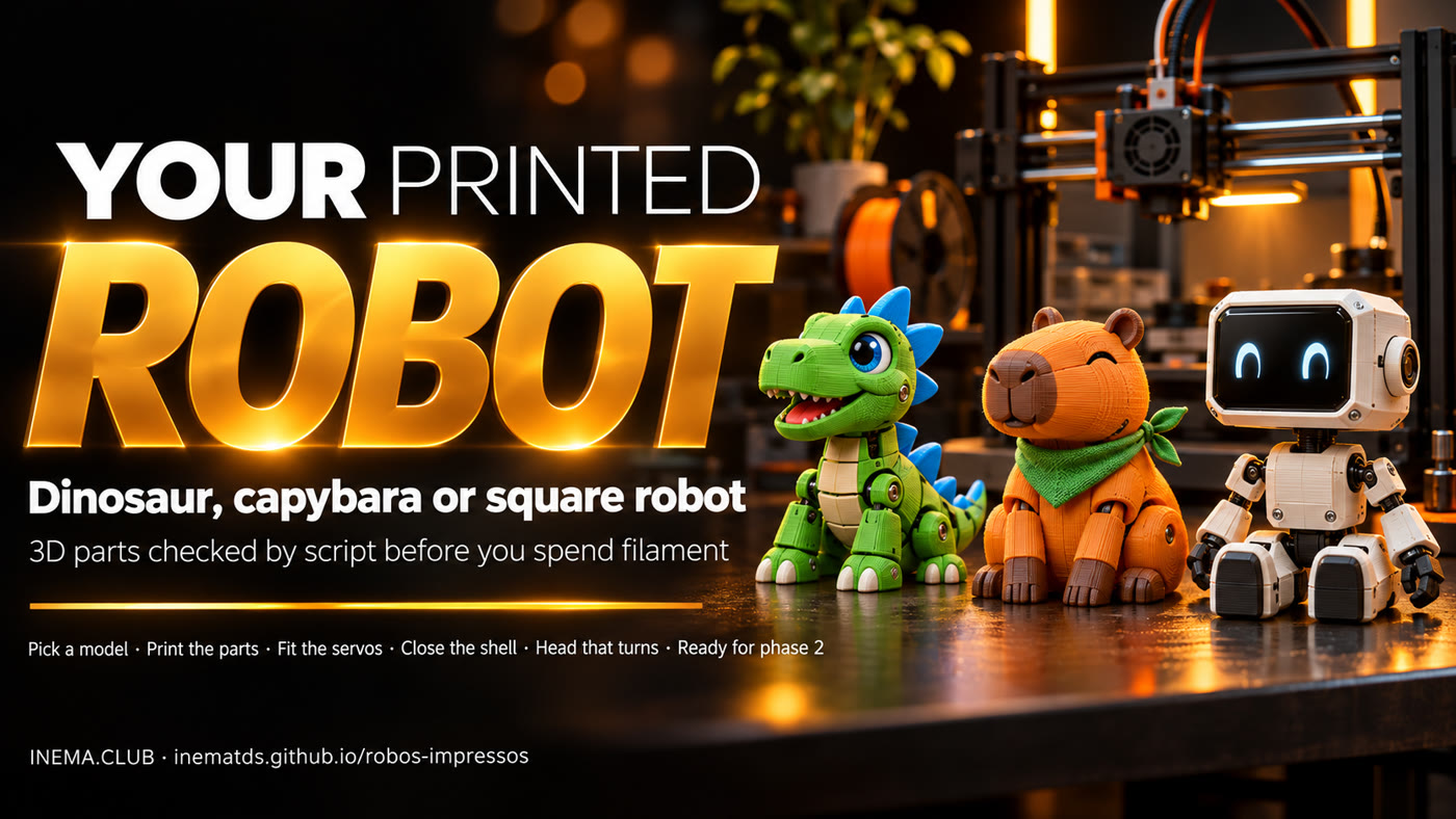
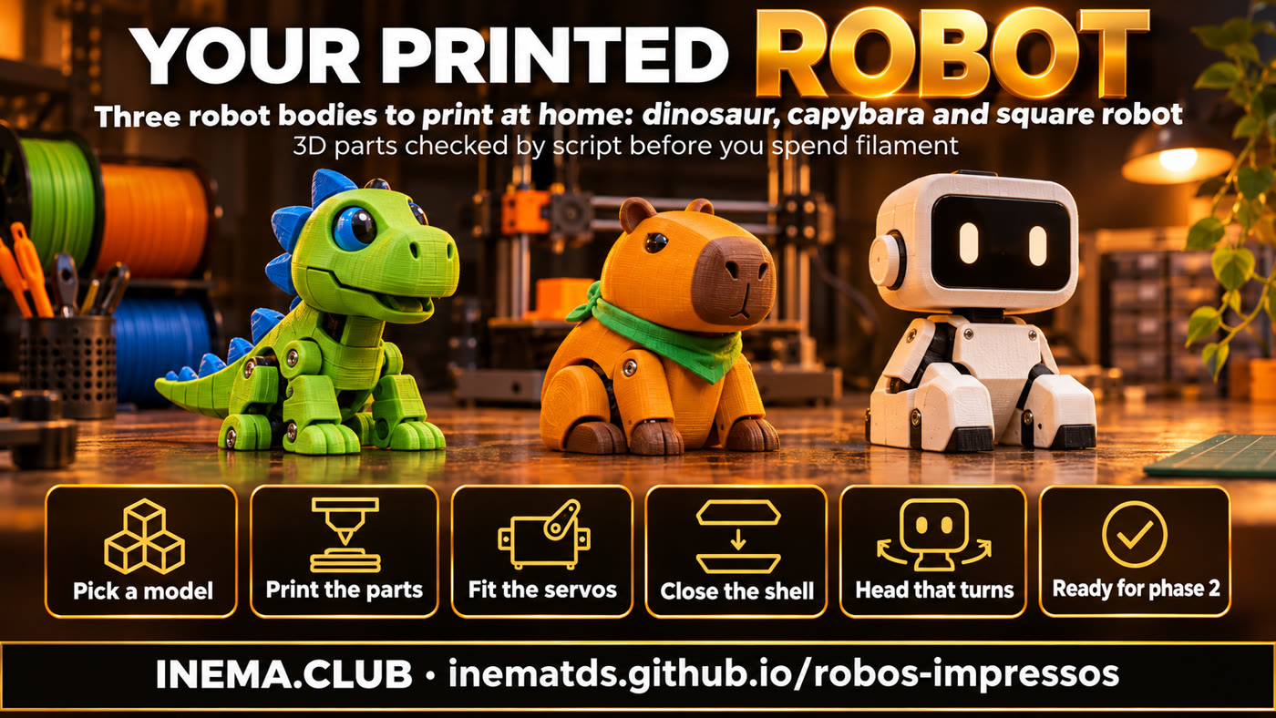
Illustration: a dinosaur, a capybara, and a toy square robot beside a 3D printer
AI-generated illustration. The real robots in the project are shown in the renders below: the square robot, for example, is a cube on a base, with no arms or legs.
At a glance

You want to build a friendly robot at home and don’t know where to start with the body. robos-impressos is a set of three robot bodies to 3D print: a dinosaur and a capybara about 33 cm tall that roll across the floor, and a square desktop robot with a screen for a face. Each one already has the right space for the motors, servos (small motors that turn to an angle and stop), battery, and Arduino and Raspberry Pi boards. It’s for anyone with access to a 3D printer with a 256 mm build plate who wants to build, learn, or teach robotics. This is phase 1, just the body and its fittings: wiring, voice, and intelligence are for phase 2. And an honest note: this is a digital project checked by a script; no one has printed these parts yet.

Illustration showing six steps: choose a model, print, fit the servos, assemble the shell, turn the head, ready for phase 2

The two banners above are AI-generated illustrations. The other images on this page are renders (computer-generated images made from the project files, not photos of an assembled robot) and a drawing of the test part.

The 3 robots

Choose yours

All three use the same servos and screws. The dinosaur and capybara share the same skeleton inside: only the shell changes.

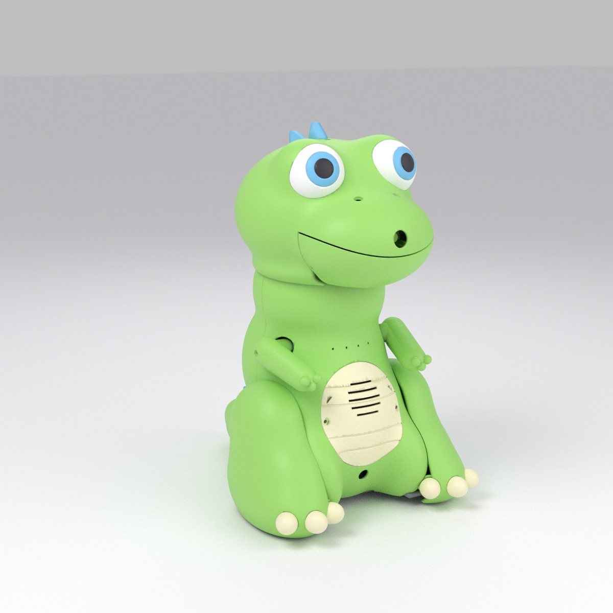
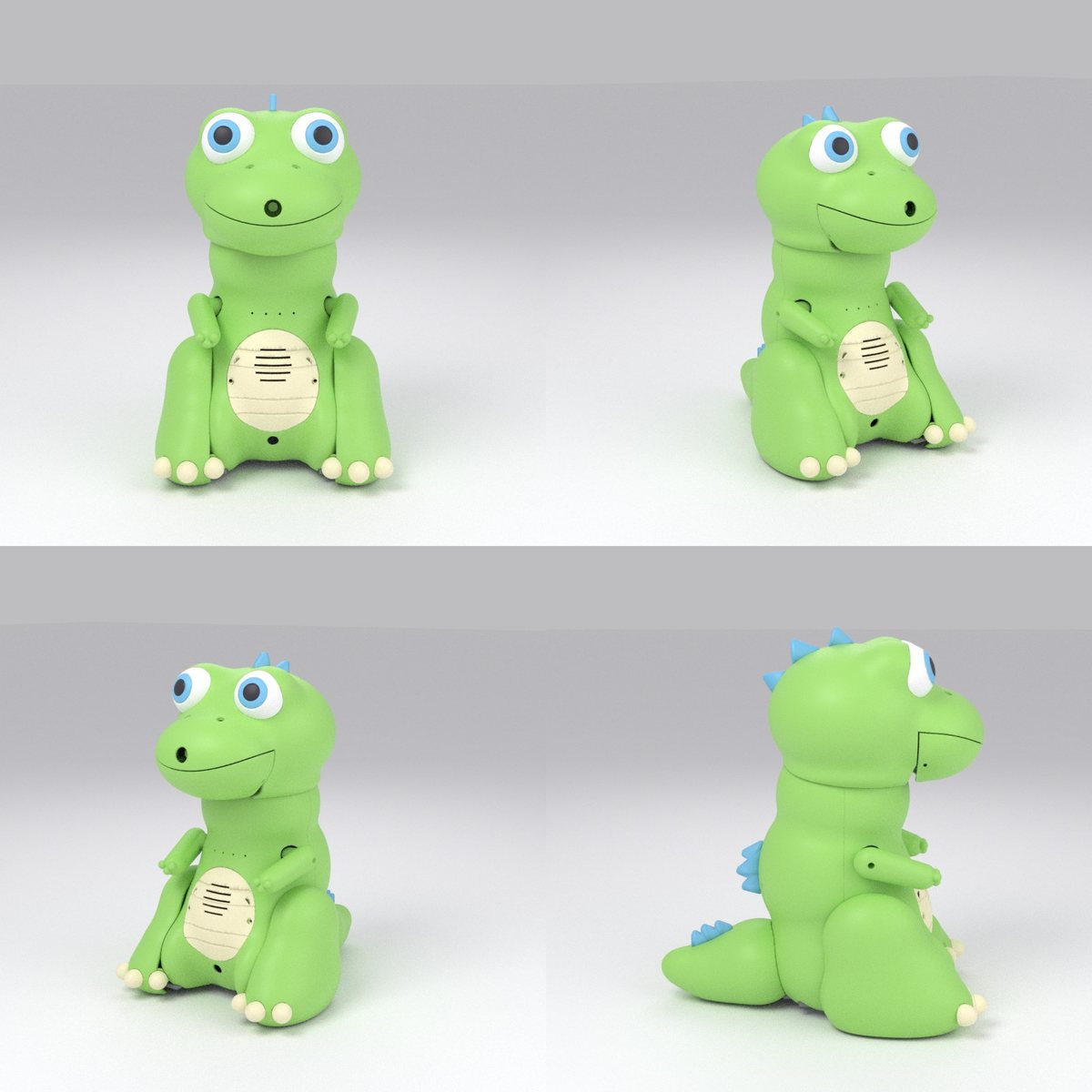
Render of the assembled dinosaur: green, with big blue eyes, a cream belly, and blue spikes

🦖 Dinosaur

A big-eyed baby dinosaur with blue spikes. It rolls on two wheels hidden inside its legs and rests on a ball. It turns and tilts its head, opens its mouth, and moves both arms.

5 servos + 2 motors

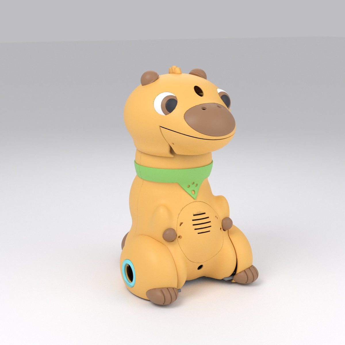
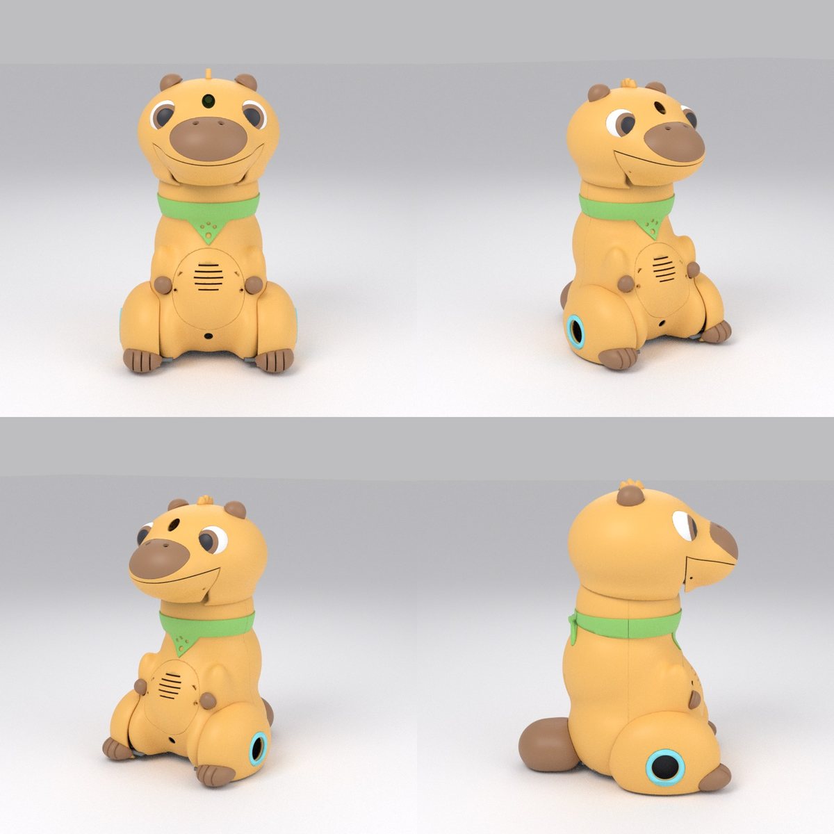
Render of the assembled capybara: orange, with a brown snout, green bandana, and blue ring around the thigh

🦫 Capybara

Seated, with a green bandana. The wheels sit inside the thighs, behind the blue ring, and the support ball sits inside the tail. It turns and tilts its head and opens its mouth.

3 servos + 2 motors

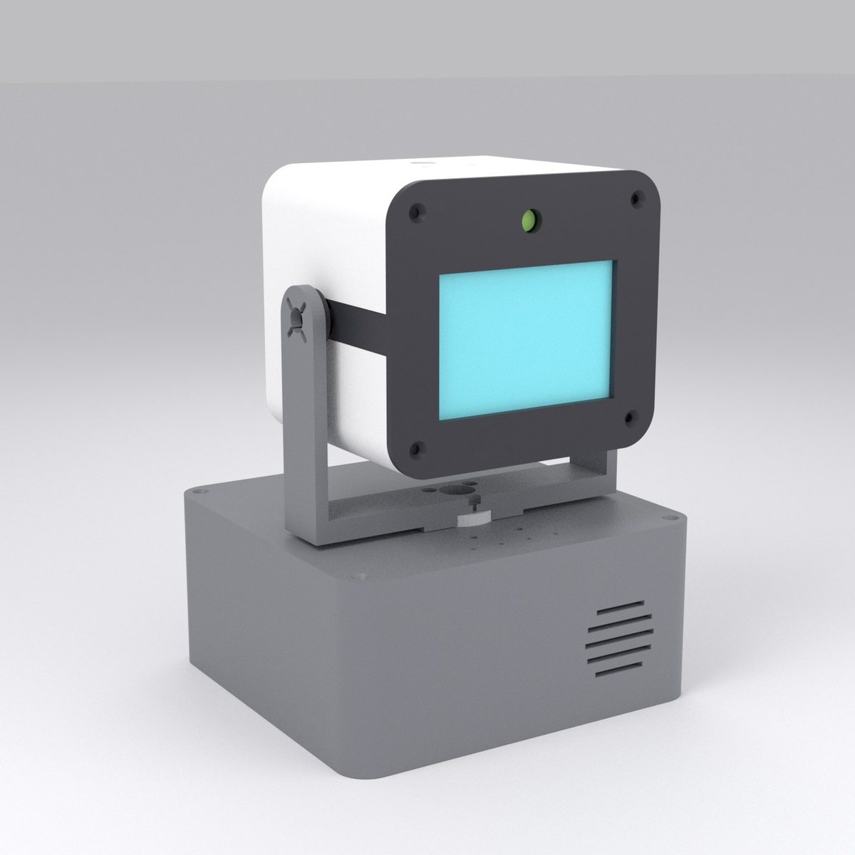
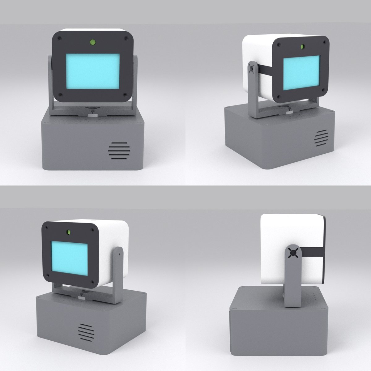
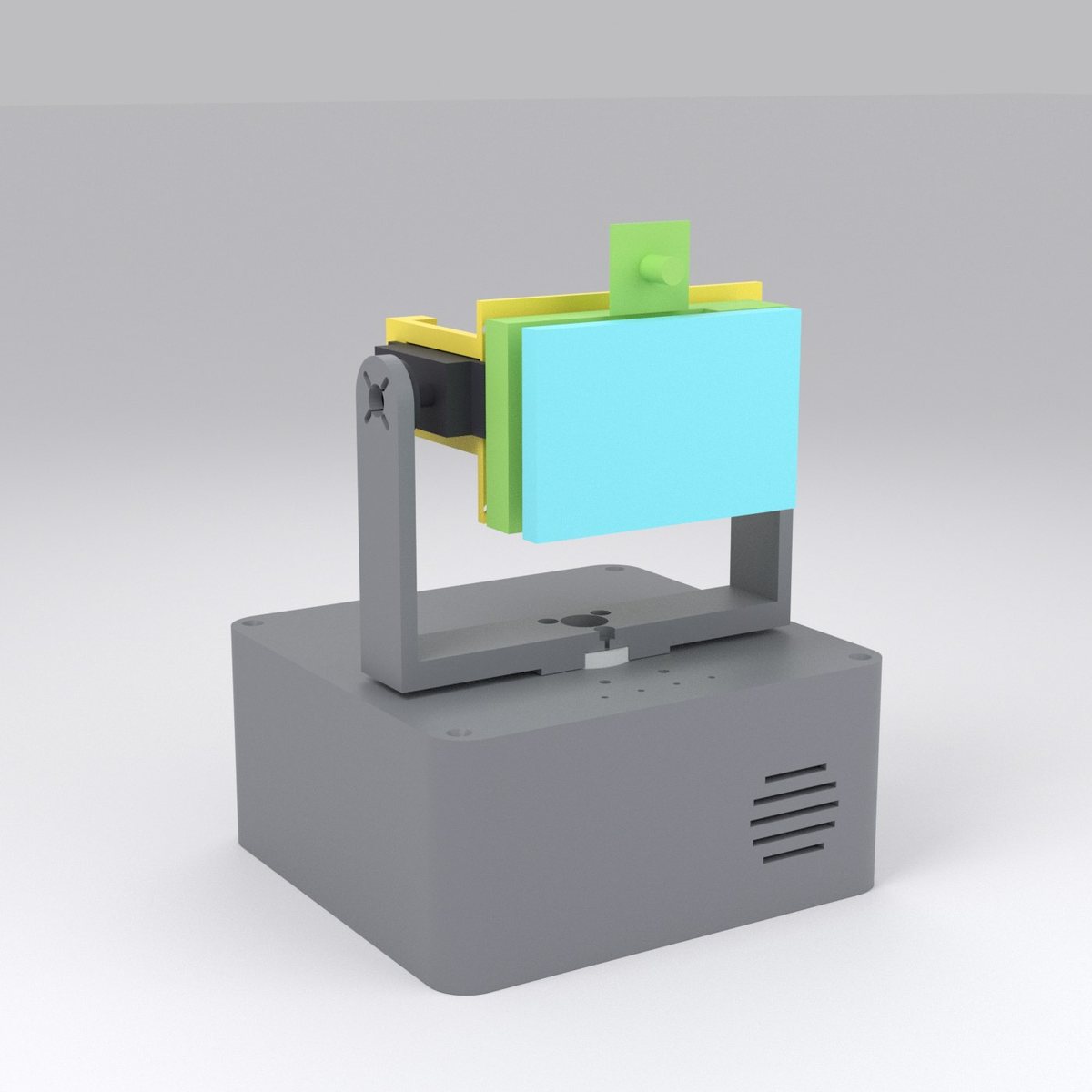
Render of the square robot: a cube-shaped head with a screen, on a fork and base

🤖 Square robot

Made for a desk; it doesn’t roll. Its head is a cube with a 3.5-inch screen that displays its eyes and mouth. It turns almost halfway around in either direction (nearly a full turn in total) and tilts up and down.

2 servos + screen

↔ on a phone, swipe the table sideways

ModelHeight (mm)PartsPlates (print jobs)Total filament (g)*Total print time (h)*Assembled robot (g)*
Dinosaur32938121107441666
Capybara32639131049421581
Square robot201148638251020

* estimate from volume, no slicer

The animals ended up 33 cm tall, a little above the 30 cm target: the battery, Arduino, and Raspberry Pi need to fit stacked inside. Parts list for each one: see the technical guide ↓

How they move

Inside: a skeleton with the shell on top

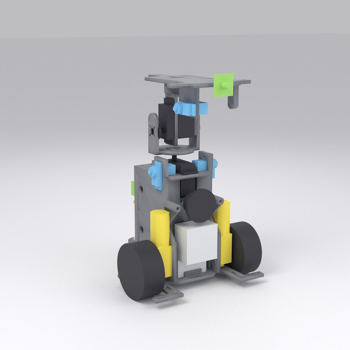
The dark skeleton bears the weight. The colorful shell only covers it: it comes off in sections without taking the skeleton apart.

Render showing only the dinosaur’s skeleton: chassis, wheels, motors, board trays, and neck

The skeleton

One piece forms the floor, the walls where the motors are screwed in, and the neck support. The Arduino tray and Raspberry Pi tray slide between the walls like drawers. The battery sits underneath them.

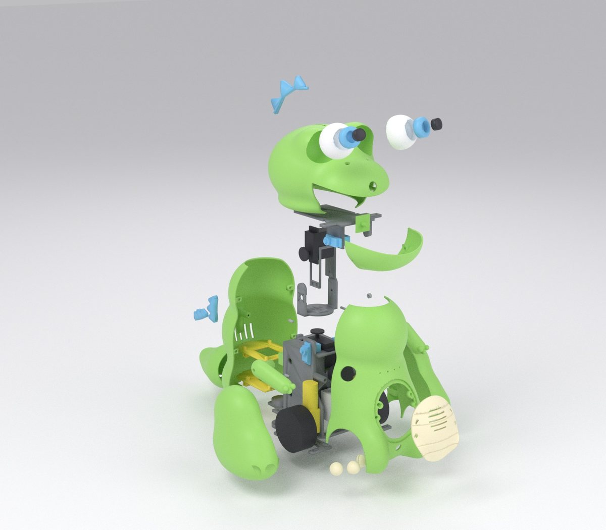
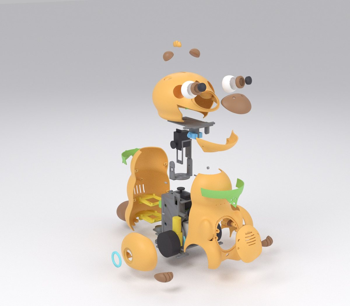
Render of the dinosaur exploded view, with each part spaced apart

The shell in parts

The belly, back, legs, tail, and head are separate parts, held together by hidden screws. To reach the boards, remove the head, tail, and back (7 screws), then slide the trays out like drawers.

Render of the capybara from four angles

Neck without a neck

The top of the body is a sphere, and the head is a helmet that turns and tilts around it with 2 mm of clearance (3 mm for the capybara). That lets the head move in every direction without leaving a gap.

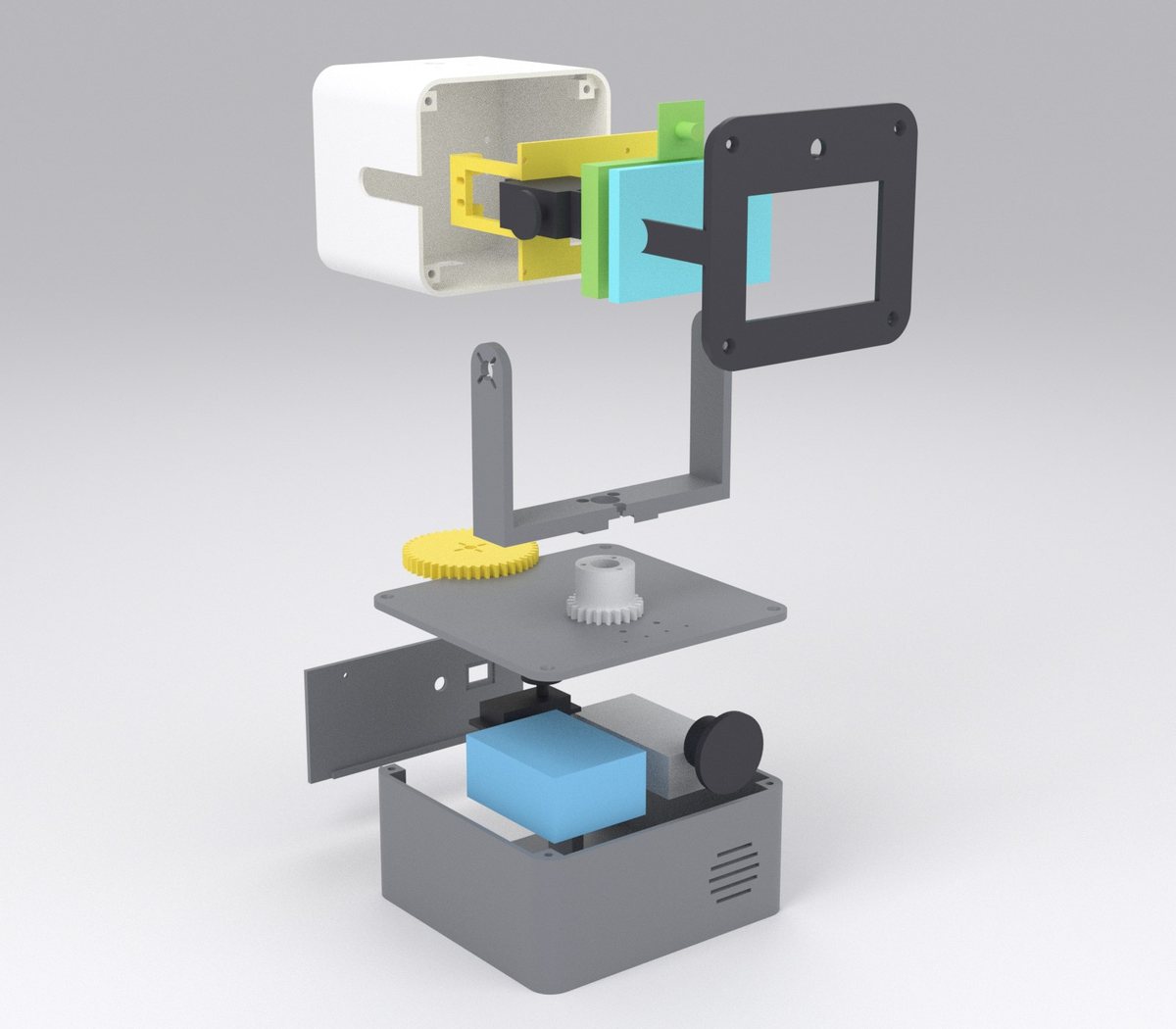
Exploded view render of the square robot: base, gears, fork, frame, head, and screen frame

The square one turns almost a full rotation

A standard servo only turns halfway. Two printed gears double that rotation, and the cables run up inside the hollow neck tube without getting tangled.

↔ on mobile, drag the table sideways

Movement (range checked to make sure no parts collide)DinosaurCapybaraSquare robot
Head side to side±60°±60°±170°
Head up and down−15° … +20°−15° … +20°−25° … +30°
Mouth0 … 18°0 … 18°drawn on the screen
Arms−15° … +40°stationary—
Movementrolls on the floorrolls on the floorstays on the table

These are the mechanical limits. The servos and program actually make it move; that is phase 2.

What was checked

Checked before using any filament

A script (a small program) opens the print files, assembles the robot on the computer, and looks for problems. These are the numbers from the latest run, across all three models.

91parts to print, all closed and complete in the file
0parts intersecting one another, across all tested positions
2.35 mmthe thinnest wall measured in the shells (the target was at least 2 mm)
226 mmis the largest part; the printer's build plate is 256 mm

Estimated print hours per model (without a slicer: approximate only)

Dinosaur~44 h
Capybara~42 h
Square robot~25 h

✅ What the script guarantees

  • Each file is a closed solid made of a single body.
  • Every part fits on the 256 × 256 × 256 mm build plate.
  • No part occupies the space of another part or a component (servo, motor, board, battery), with the head, mouth, and arms at the extremes.
  • Every part can reach its position: the script brings them in one at a time, in assembly order, and flags any collision with what is already assembled.
  • No part is floating in the air, and the center of gravity falls inside the supports, with clearance.
  • The test itself is tested: one part is deliberately moved 3 mm, and the script must flag it.

⚠️ What only printing can tell you

  • No one has printed or assembled these parts yet.
  • Print time and filament use are volume-based estimates.
  • Some component dimensions have no official source (servo tabs, motor driver holes). They are marked NC in cad/parametros.py and section 4 of PLANO.md (in Portuguese): measure your part with calipers and, if it differs, change the number and generate the parts again.
  • The script does not test strength, whether a screwdriver can reach every screw, or the 3 mm fit of the servos in the arms and mouth.
Action plan

From file to assembled robot body

Five steps, no programming needed. At the end, you have the assembled body, with servos and motors in place; making it move is phase 2.

1
Choose a modelThe square robot has fewer parts (14), but needs a Raspberry Pi and screen. The dinosaur and capybara each have about 38 parts, and you can swap one shell for the other later.
2
Buy the minimum for testingOne pack of M3 threaded inserts, some M3 screws, and a soldering iron are enough for the test; for the animals, you also need a micro servo (the square robot does not use one). The rest (servos, wheel motors, battery holder, switch) are common parts at electronics shops in Brazil. The servos and motors are only for checking the fit at this stage: they will not move yet.
3
Print the test part firstIt’s a 7 cm test plate that checks the fit of the micro servo, inserts, screws, and guide pin on your printer. Less than an hour of printing can save you from redoing a five-hour part. If everything fits, you can continue without installing anything.
4
Print by colorThe parts come laid out in the right orientation and separated by color. The skeleton is printed in PETG, which is more durable; the shell in PLA.
5
Assemble from the inside outFirst the skeleton with motors and servos, then the shell, and finally the head. The order, screw by screw, is in the project plan.

Files, commands, and the shopping list are in the technical section: see the technical guide ↓

Words on this page

If any of these names are new to you

Servo
A small motor that turns to an angle and stops there. It turns the head and opens the mouth.
Arduino and Raspberry Pi
Two electronic boards. Arduino controls motors and servos; Raspberry Pi is a small computer that handles voice and camera in phase 2.
Script
A small program. Here, it generates the parts and checks that they’re correct.
Render
An image made on a computer from the 3D file. It isn’t a photo.
PLA and PETG
Two printing plastics. PLA gives a nice finish; PETG handles more force and heat.
Build plate
The printer’s base. “12 build plates” means 12 prints, one after another.
M3 insert
A threaded brass sleeve that goes into the plastic while hot so the 3 mm screw holds firmly.
18650 battery
A rechargeable lithium battery, a little larger than a regular battery.
Motor driver
A small board that lets Arduino start and reverse the wheel motors.
TT motor
The small yellow geared motor commonly used in robotics cars.
Shield
A board that fits on top of Arduino to make connecting the servos easier.
Rocker switch
The on/off switch.
Chassis, fork and cradle
Skeleton parts: the chassis is the base with the walls; the fork and cradle are the two neck parts.
Pan, tilt, horn and CG
Terms in the checker output: pan means turning side to side; tilt means angling up and down; horn is the small part attached to the servo shaft; CG is the center of gravity.
Guide pin
A printed 4 mm pin that aligns the front and back halves of the torso. The hole it goes into is the socket.
NC
Not confirmed: a component measurement without an official source that you check on your own part.
Technical section

The kit: for anyone who wants to print, change dimensions, or create another model

You don't need this section to understand what you've read above.

What the kit is

Parts generated from code, not drawn by hand

Everything comes from a file of measurements. If you change the servo or your printer’s clearance, change one number and generate it again.

📐 A file of measurements

cad/parametros.py stores clearances, measurements for each component (with the source next to it), and the shape of each robot.

🔍 Checker with 9 tests

cad/verificar.py reads the exported STL files and rejects open parts, oversized parts, thin walls, parts intersecting each other, parts that cannot reach their position, and robots that tip over.

🦴 Shared skeleton

The chassis, trays, fork, and neck cradle use the same files for the dinosaur and the capybara (pecas/comum/).

How it works

From measurements to print files

The animals’ outer shells are made by adding rounded shapes together and turning them into a mesh; holes, pockets, and cuts are exact operations applied on top.

cad/parametros.py→ cad/gerar.py→ pecas/<modelo>/stl + 3mf + montagem.json→ cad/verificar.py→ cad/renders.sh

Generate

Creates STL and 3MF files for each part, already oriented for printing, the complete assembly (montagem.glb), and the build plate layouts.

Check

Assembles the robot from the files, moves the joints to their limits, measures overlaps by shared volume, and rebuilds the assembly one part at a time.

Render

Blender produces the images on this page: assembled, exploded, skeleton, and build plates.

Prerequisites

What you need

To just print, all you need is a printer, a slicer, and the ZIP download. Python and Blender are for anyone who wants to change the project.

For printing

A printer with a 256 mm build plate (the project was designed for the Bambu Lab A1; it does not fit on a 220 mm plate because the largest part is 226 mm), PLA and PETG filament, a slicer such as Bambu Studio, and the components on the shopping list.

To generate the parts

Python 3.12 or later (download it from python.org; the library versions require it) and git. The libraries are installed in an isolated environment inside the folder.

# check if you already have it
python3 --version
git --version

For the images (optional)

Blender 4. It is only used for the renders.

# check if you already have it
blender --version
User guide · step by step

Download, print, and assemble

These are the repository commands. The complete assembly sequence, with every screw, is in PLANO.md (in Portuguese).

1

Download the project

The print files are ready in the pecas/ folder, in STL and 3MF formats. If you only want to print, download the ZIP (about 80 MB), extract it, and open the files in your slicer: you do not need a terminal or Python. The componentes/ folders are only outlines of purchased parts: do not print them.

Download everything as a ZIP

If you want to change dimensions and regenerate the parts, you can clone the repository with git in a terminal:

git clone https://github.com/inematds/robos-impressos.git
cd robos-impressos
ls pecas/dino/stl pecas/capivara/stl pecas/cubo/stl pecas/comum/stl
2

Print the test part

Print the test part and, for the dinosaur or capybara, a guide pin (pecas/comum/stl/comum-pino-guia.stl). The drawing below shows each hole from above. Next to the micro servo window are three threaded insert holes (3,9, 4,0, and 4,1 mm), and at the tip is the larger hole for the yellow motor shaft (the shaft must turn freely). In the other row are three guide pin sockets (clearances of 0,20, 0,25, and 0,30 mm) and four screw holes: M3 free fit, M3 that cuts a thread in the plastic (M3* in the drawing), M2,5, and M2. The project uses the 4,0 mm hole and the 0,25 mm socket, the middle ones, marked with a small dimple (● in the drawing). The M3 threaded insert (the brass bushing that is inserted hot with a soldering iron and becomes a thread) must fit firmly; the pin must fit snugly, without hammering it in. The micro servo must fit into the window by hand, without forcing it or letting it wobble. The screws must pass freely through the free-fit M3 hole and cut threads in the other three. If everything fits, keep going. If the neighboring hole or socket fits better, or if the servo is too tight, adjust the clearance in cad/parametros.py, in the FOLGA block (componente for the servo, encaixe for the pin, inserto_d for the insert), then regenerate the parts from step 3: that’s the only time you need Python.

# open this file in the slicer
pecas/comum/stl/comum-teste-encaixe.stl
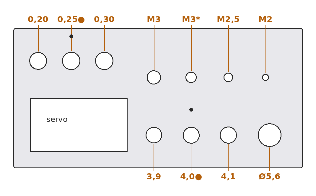
Drawing of the test piece from above, with the measurement of each hole

tap the drawing to enlarge

view the test part on GitHub (download button on the page)

3

Generate and check (only if you changed a measurement)

The first command recreates all the parts; the second runs the 9 tests and exits with an error if any fail.

python3 -m venv .venv
.venv/bin/pip install -r requirements.txt
# takes a few minutes
.venv/bin/python cad/gerar.py todos
.venv/bin/python cad/verificar.py todos

These commands are for Linux and macOS. On Windows, use python instead of python3, dir instead of ls, .venv\Scripts\pip instead of .venv/bin/pip, and .venv\Scripts\python instead of .venv/bin/python.

4

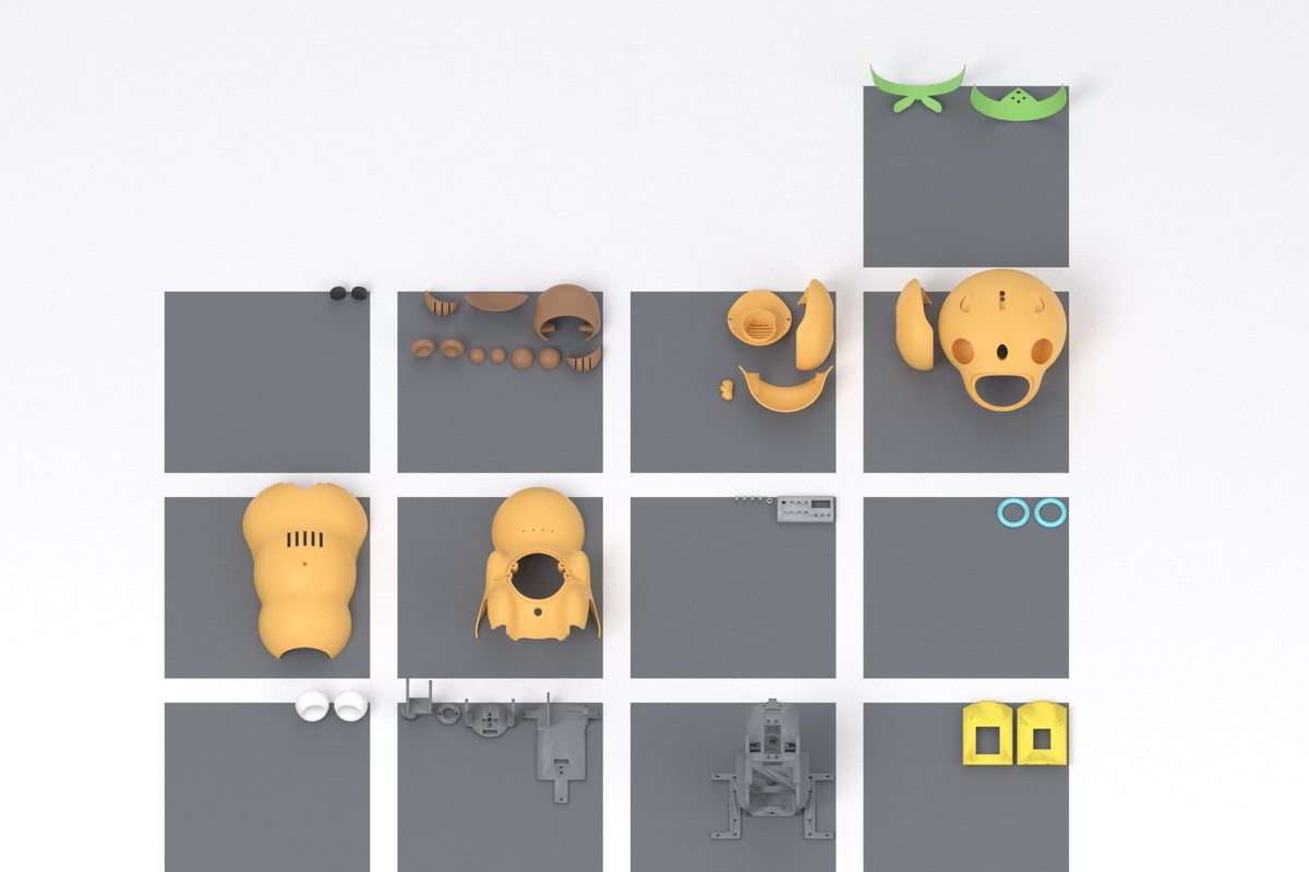
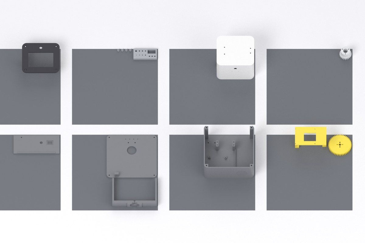
Print the build plates

Each build plate below is one print: the parts are already laid flat, grouped by color and material, in a 3MF file with the geometry (the file doesn’t include slicer settings and hasn’t been opened in a slicer yet; if yours won’t open it, use the separate STL files in pecas/<modelo>/stl and pecas/comum/stl (chassis, trays, and animal neck parts), along with the table). The file name is <modelo>-mesa-NN-material-cor.3mf. Untested starting point: 0,2 mm layer height, 0,4 mm nozzle, 3 walls, and 15 % infill. The rounded shells need tree supports; the skeleton prints without supports, except for berco-tilt. The test part and guide pins are repeated on the gray build plate: if you’ve already printed them, remove them from the plate. The colors are just for appearance: at minimum, you need one roll of PETG for the skeleton and one of PLA for the shell. In the tables, mesa-cabeca is a part name (the part that supports the head from inside).

# one 3MF file per build plate, for each model
pecas/dino/mesas/     pecas/capivara/mesas/     pecas/cubo/mesas/

🦖 Dinosaur
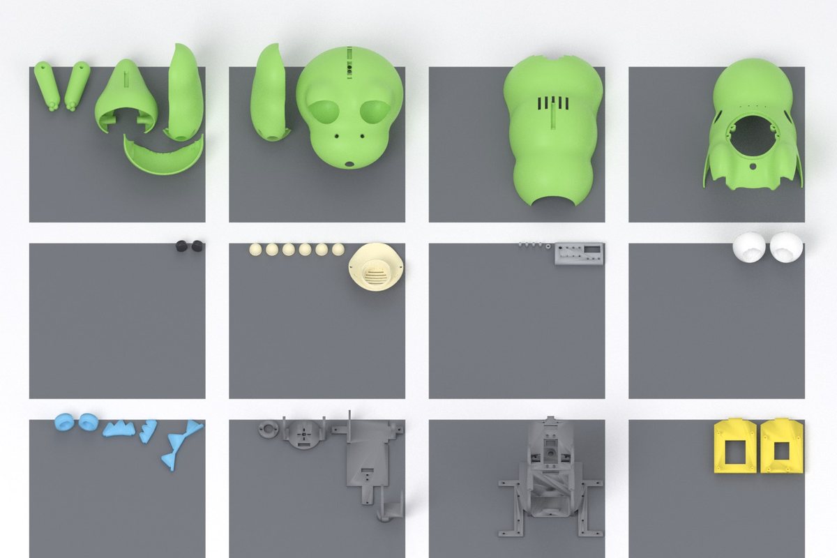
Render of the build plates, with parts laid flat and separated by color

↔ on a phone, swipe the table sideways

PlateMaterialColourPart
1PETGyellowbandeja-uno, bandeja-pi
2PETGgraphitechassi
3PETGgraphitemesa-cabeca, garfo-pescoco, capa-esfera, berco-tilt
4PLAbluecrista-cabeca, crista-cauda, crista-costas, iris, iris-esq
5PLAwhiteolho, olho-esq
6PLAgreyteste-encaixe, bucha-eixo, pino-guia ×4
7PLAcreambarriga, unha ×6
8PLAblackpupila, pupila-esq
9PLAgreentorso-frente
10PLAgreentorso-costas
11PLAgreencranio, perna-dir
12PLAgreenperna-esq, cauda, braco-dir, braco-esq, mandibula

🦫 Capybara

Render of the build plates, with parts laid flat and separated by color

↔ on a phone, swipe the table sideways

PlateMaterialColourPart
1PETGyellowbandeja-uno, bandeja-pi
2PETGgraphitechassi
3PETGgraphitemesa-cabeca, garfo-pescoco, capa-esfera, berco-tilt
4PLAwhiteolho, olho-esq
5PLAcyanaro ×2
6PLAgreyteste-encaixe, bucha-eixo, pino-guia ×4
7PLAorangetorso-frente
8PLAorangetorso-costas
9PLAorangecranio, coxa-dir
10PLAorangecoxa-esq, barriga, mandibula, topete
11PLAbrownrabo, focinho, pata-dir, pata-esq, orelha ×2, mao ×2, iris, iris-esq
12PLAblackpupila, pupila-esq
13PLAgreenbandana-frente, bandana-costas

🤖 Square robot

Render of the build plates, with parts laid flat and separated by color

↔ on a phone, swipe the table sideways

PlateMaterialColourPart
1PETGyellowengrenagem-servo, quadro-cabeca
2PETGgraphitebase
3PETGgraphitetampa-base, garfo
4PETGgraphiteporta-traseira
5PETGsilvertubo-pescoco
6PLAwhitecabeca-corpo
7PLAgreyteste-encaixe, espacador-pi ×4
8PLAblackcabeca-face
5

Assemble one of the animals

Assembly order for the dinosaur and capybara:

  1. Install the M3 threaded inserts while hot.
  2. Screw the two motors onto the chassis walls (the large dark part, which is the skeleton), from the outside, with the motor facing up.
  3. Attach the support ball with its cover underneath, and snap the on/off switch into the floor.
  4. Mount the head-turning servo at the top of the chassis, then the fork, the second servo, and the cradle (the two neck parts).
  5. For the dinosaur, install the two arm micro servos in the wall windows now.
  6. Install the battery, motor driver, and board trays.
  7. Close the torso at the front, then fit the wheels through the sides.
  8. Belly panel, back, legs or thighs, tail.
  9. Assemble the head on the workbench (the mesa-cabeca part goes under the skull; then add the mouth servo, jaw, and eyes) and lower the whole assembly onto the neck: two screws from above.
  10. The head crest (or tuft) and back crest cover screws: press them into place, without glue. Nails, ears, hands, and bandana can be glued on.
  11. For the dinosaur, attach the arms to the micro servos last.
  12. There are 20 steps in section 6 of PLANO.md (in Portuguese).
6

Or assemble the square robot

Assembly order:

  1. Servo on the base floor and Arduino beside it; then the large gear on top of the servo.
  2. Insert the battery through the rear door.
  3. Neck tube under the cover, then the cover on the base.
  4. Fork on top of the tube, with three long screws.
  5. Raspberry Pi, screen, and the second servo on the head frame.
  6. Head shell from the rear, screen frame from the front.
  7. Head between the fork arms and the rear door.

🦖 Dinosaur — parts to print

↔ on a phone, swipe the table sideways

PartSize on the bed (mm)QtyMaterialColourSupportsFilament (g)*Time (h)*
torso-frente145 × 226 × 961PLAgreenyes1224.7
torso-costas145 × 226 × 741PLAgreenyes1365.2
barriga79 × 87 × 261PLAcreamyes241.0
crista-costas47 × 27 × 61PLAblueno50.3
pino-guia (shared)4 × 4 × 94PLAgreyno00.3
perna-dir60 × 127 × 1131PLAgreenno552.1
perna-esq60 × 127 × 1131PLAgreenno552.1
unha18 × 18 × 136PLAcreamno131.0
cauda92 × 112 × 691PLAgreenno552.1
crista-cauda26 × 38 × 61PLAblueno40.2
cranio156 × 184 × 1201PLAgreenyes1877.1
mandibula116 × 59 × 491PLAgreenyes261.1
mesa-cabeca104 × 138 × 361PETGgraphiteno411.6
crista-cabeca61 × 83 × 61PLAblueno70.4
olho48 × 38 × 481PLAwhiteno180.8
olho-esq48 × 38 × 481PLAwhiteno180.8
iris29 × 19 × 291PLAblueno50.3
iris-esq29 × 19 × 291PLAblueno50.3
pupila17 × 13 × 181PLAblackno20.1
pupila-esq17 × 13 × 181PLAblackno20.1
bucha-eixo (shared)7 × 7 × 31PLAgreyno00.1
braco-dir38 × 73 × 311PLAgreenyes160.7
braco-esq38 × 73 × 311PLAgreenyes160.7
chassi (shared)152 × 190 × 1481PETGgraphiteno2067.6
capa-esfera (shared)29 × 29 × 61PETGgraphiteno30.2
bandeja-uno (shared)61 × 90 × 161PETGyellowno190.8
bandeja-pi (shared)61 × 90 × 161PETGyellowno160.7
garfo-pescoco (shared)65 × 48 × 511PETGgraphiteno170.7
berco-tilt (shared)38 × 23 × 771PETGgraphiteyes150.6
teste-encaixe (shared)70 × 34 × 81PLAgreyno150.6
Total38110744

* estimate from volume, no slicer

🦫 Capybara — parts to print

↔ on a phone, swipe the table sideways

PartSize on the bed (mm)QtyMaterialColourSupportsFilament (g)*Time (h)*
torso-frente156 × 226 × 961PLAorangeyes1335.0
torso-costas156 × 226 × 741PLAorangeyes1395.3
barriga79 × 87 × 291PLAorangeyes261.1
bandana-frente119 × 47 × 601PLAgreenyes90.4
bandana-costas119 × 38 × 671PLAgreenyes100.5
mao20 × 20 × 112PLAbrownno50.3
pino-guia (shared)4 × 4 × 94PLAgreyno00.3
coxa-dir46 × 119 × 821PLAorangeyes371.5
coxa-esq46 × 119 × 821PLAorangeyes371.5
aro40 × 40 × 32PLAcyanno40.3
pata-dir44 × 37 × 251PLAbrownno100.5
pata-esq44 × 37 × 251PLAbrownno100.5
rabo84 × 72 × 501PLAbrownyes341.4
cranio160 × 185 × 1141PLAorangeyes1796.8
mandibula119 × 58 × 441PLAorangeyes210.8
focinho79 × 41 × 401PLAbrownyes120.5
mesa-cabeca98 × 140 × 331PETGgraphiteno401.5
orelha28 × 28 × 152PLAbrownno90.5
topete16 × 26 × 61PLAorangeno20.2
olho42 × 29 × 421PLAwhiteno130.6
olho-esq42 × 29 × 421PLAwhiteno130.6
iris30 × 15 × 301PLAbrownno50.2
iris-esq30 × 15 × 301PLAbrownno50.2
pupila21 × 11 × 211PLAblackno20.2
pupila-esq21 × 11 × 211PLAblackno20.2
bucha-eixo (shared)7 × 7 × 31PLAgreyno00.1
chassi (shared)152 × 190 × 1481PETGgraphiteno2067.6
capa-esfera (shared)29 × 29 × 61PETGgraphiteno30.2
bandeja-uno (shared)61 × 90 × 161PETGyellowno190.8
bandeja-pi (shared)61 × 90 × 161PETGyellowno160.7
garfo-pescoco (shared)65 × 48 × 511PETGgraphiteno170.7
berco-tilt (shared)38 × 23 × 771PETGgraphiteyes150.6
teste-encaixe (shared)70 × 34 × 81PLAgreyno150.6
Total39104942

* estimate from volume, no slicer

🤖 Square robot — parts to print

↔ on a phone, swipe the table sideways

PartSize on the bed (mm)QtyMaterialColourSupportsFilament (g)*Time (h)*
base150 × 144 × 661PETGgraphiteno2208.1
tampa-base150 × 144 × 181PETGgraphiteno943.5
porta-traseira137 × 62 × 51PETGgraphiteno321.3
tubo-pescoco36 × 36 × 281PETGsilverno150.6
engrenagem-servo69 × 69 × 81PETGyellowno230.9
garfo133 × 92 × 241PETGgraphiteno401.6
quadro-cabeca94 × 60 × 551PETGyellowno301.2
cabeca-corpo112 × 100 × 891PLAwhiteno1355.1
cabeca-face112 × 100 × 431PLAblackno341.3
espacador-pi6 × 6 × 54PLAgreyno00.3
teste-encaixe (shared)70 × 34 × 81PLAgreyno150.6
Total1463825

* estimate from volume, no slicer

Shopping list

↔ on mobile, drag the table sideways

ItemDinosaurCapybaraSquare robot
MG996R standard servo222
SG90 or MG90S micro servo31—
Yellow 1:48 TT motor with 65 mm wheel22—
16 mm steel ball11—
Holder for 2 18650 batteries, with batteries111
Small rocker switch (KCD11)111
Raspberry Pi 4 or 5optionaloptional1
3.5-inch screen for Raspberry Pi, model MPI3501 (fits the board pins; an HDMI screen will not work)——1
L298N motor driver11—
M3 threaded inserts (5,7 mm long, for a 4,0 mm hole)252514
M3 screws, 6 to 25 mm long, M3 nuts and washers (and some M2,5)kitkitkit
Arduino Uno with servo shieldoptionaloptionaloptional
4 adhesive rubber feet——4

In phase 1, nothing is powered on: Arduino and Raspberry Pi are only used to check the fit, so they’re optional (in the square robot, the Raspberry Pi holds the screen). Screws outside the common kit: for the animals, 2 M3×12 flat-head screws and 4 M2,5×8; for the square robot, 3 M3×35, 8 M3×10 flat-head screws, and 4 M2,5×12. In M3×12, 3 is the diameter and 12 is the length, in millimeters. The full list is in section 3 of PLANO.md (in Portuguese), and the quantity for each step is in section 6.

Estimated component cost, including Arduino and shield but excluding the printer and filament: R$ 330 to 560 per animal. For the square robot, R$ 260 to 430 plus the Raspberry Pi and screen, which are required for that model (estimated additional cost of R$ 490 to 850). Prices from Brazilian shops in November 2026; estimate.

Tools: soldering iron (for the inserts), small Phillips screwdriver, 2.5 mm Allen key, calipers (to measure your components), and instant glue.

Be careful with 18650 batteries: they are lithium batteries. Use a proper holder and charger, keep the terminals from touching metal, and don't charge them unattended, especially with children nearby.
Examples

What the parts look like

Renders generated by the project itself.

Dinosaur from four angles
Capybara in exploded view
Open capybara: the same structure as the dinosaur inside
Square robot from four angles
Square robot frame without the shell
Square robot without the head shell: frame, Raspberry Pi, and screen

Verifier output

Summary of what the script prints, in Portuguese. The full text is in pecas/verificacao-saida.txt.

== dino
  [PASSOU] 1 contagem: 30 peças distintas, 38 no total (esperado 38); faltando 0; sobrando 0
  [PASSOU] 2 malha: 30 STL fechados, 1 corpo cada
  [PASSOU] 3 mesa: todas cabem em 256 x 256 x 256 mm; maior dimensão 226.4 mm (torso-frente)
  [PASSOU] 4 parede: torso 2.36–2.41 mm; cabeça 2.36–2.42 mm; perna 2.35–2.41 mm; cauda 2.35–2.41 mm (mínimo exigido 2.0)
  [PASSOU] 5 interferência: 54 sólidos (37 impressos + 17 componentes), 12 poses, 0 sobreposições; 2 encaixe(s) previsto(s) fora da conta: motor-tt-dir x roda-dir (eixo do motor entra no cubo da roda); motor-tt-esq x roda-esq (eixo do motor entra no cubo da roda)
  [PASSOU] 6 teste negativo: 'chassi' deslocada 3 mm em X → 13 sobreposições acusadas (tem que ser > 0)
  [PASSOU] 7 peça solta: as 37 peças montadas encostam (≤ 1.5 mm) em outra
  [PASSOU] 8 equilíbrio: massa estimada 1666 g; CG neutro em x=0.1 y=-26.1 z=118.2 mm, margem 26.1 mm (tomba com 12°); pior pose 'tilt-baixo': margem 22.1 mm (11°); mínimo exigido 10 mm
  [PASSOU] 9 caminho: 31 passos (montagem + abertura para manutenção), cada peça entra ou sai pela direção declarada sem atravessar o que está montado
== capivara
  [PASSOU] 1 contagem: 33 peças distintas, 39 no total (esperado 39); faltando 0; sobrando 0
  [PASSOU] 2 malha: 33 STL fechados, 1 corpo cada
  [PASSOU] 3 mesa: todas cabem em 256 x 256 x 256 mm; maior dimensão 226.4 mm (torso-frente)
  [PASSOU] 4 parede: torso 2.36–2.41 mm; cabeça 2.36–2.41 mm; coxa 2.36–2.40 mm; rabo 2.36–2.41 mm (mínimo exigido 2.0)
  [PASSOU] 5 interferência: 53 sólidos (38 impressos + 15 componentes), 8 poses, 0 sobreposições; 2 encaixe(s) previsto(s) fora da conta: motor-tt-dir x roda-dir (eixo do motor entra no cubo da roda); motor-tt-esq x roda-esq (eixo do motor entra no cubo da roda)
  [PASSOU] 6 teste negativo: 'chassi' deslocada 3 mm em X → 12 sobreposições acusadas (tem que ser > 0)
  [PASSOU] 7 peça solta: as 38 peças montadas encostam (≤ 1.5 mm) em outra
  [PASSOU] 8 equilíbrio: massa estimada 1581 g; CG neutro em x=-0.0 y=-24.9 z=117.4 mm, margem 24.9 mm (tomba com 12°); pior pose 'tilt-baixo': margem 21.0 mm (10°); mínimo exigido 10 mm
  [PASSOU] 9 caminho: 27 passos (montagem + abertura para manutenção), cada peça entra ou sai pela direção declarada sem atravessar o que está montado
== cubo
  [PASSOU] 1 contagem: 11 peças distintas, 14 no total (esperado 14); faltando 0; sobrando 0
  [PASSOU] 2 malha: 11 STL fechados, 1 corpo cada
  [PASSOU] 3 mesa: todas cabem em 256 x 256 x 256 mm; maior dimensão 150.0 mm (base)
  [PASSOU] 4 parede: modelo sem casca orgânica (paredes são sólidos exatos ≥ 2,4 mm)
  [PASSOU] 5 interferência: 22 sólidos (13 impressos + 9 componentes), 9 poses, 0 sobreposições; 1 encaixe(s) previsto(s) fora da conta: engrenagem-servo x servo-pan MG996R (horn do servo fica no rebaixo da engrenagem)
  [PASSOU] 6 teste negativo: 'quadro-cabeca' deslocada 3 mm em X → 1 sobreposições acusadas (tem que ser > 0)
  [PASSOU] 7 peça solta: as 13 peças montadas encostam (≤ 1.5 mm) em outra
  [PASSOU] 8 equilíbrio: massa estimada 1020 g; CG neutro em x=-2.2 y=5.0 z=74.5 mm, margem 59.0 mm (tomba com 38°); pior pose 'pan+37': margem 58.8 mm (38°); mínimo exigido 10 mm
  [PASSOU] 9 caminho: 12 passos (montagem + abertura para manutenção), cada peça entra ou sai pela direção declarada sem atravessar o que está montado
Ready for phase 2

There is already a place for everything

Phase 2 (listening, speaking, seeing, walking without bumping into things, knowing where it is) has not been built. The mechanical design already has space, holes, and cable routing.

↔ on mobile, drag the table sideways

Phase 2 componentDinosaur and capybaraSquare robot
Raspberry Pi and Arduino togethertwo trays on the rack, one above the other; ventilation slots in the backRaspberry Pi in the head, Arduino in the base
Microphones4 holes in the chest4 holes at the top of the head and 4 in the base lid
40 mm speakerring inside the belly panel; the panel slots form the grillering and grille at the front of the base
Raspberry Pi cameraposts inside the snout (dinosaur) or forehead (capybara); moves with the headposts behind the frame, above the screen
Distance and drop sensors, wheel rotation meter (encoder), tilt sensor (IMU)front window, 4 pairs of holes in the floor, 12 mm clearance above each motor, 2 holes at the top of the chassis2 pairs of holes in the base floor
Small LiDAR (a laser sensor that measures the room around it)Doesn't fit with 360° vision: the head blocks itFits on the flat top of the head
Larger battery and recharging58 × 114 × 23 mm bay that opens from the rear; hole underneath for a charging connector, so you can recharge without opening itRear door with the switch and charging connector
Roadmap

Where the project stands

No dates promised.

Done
Phase 1 on the computerThree code-generated models, checked by script, with renders and a parts list.
To do
Print and assemblePrint the test piece, measure the actual components, correct measurements without a source, and assemble the first robot.
Phase 2
Electronics, voice, vision, and AIWiring, servo program, voice control, camera, sensors, and navigation around the house.